It was expected that the engine would produce at least 500 BHP and therefore it was necessary to design the rear axle to accept that level of power. Because it was intended to use the quick-change differential unit, there was a limit on the size of axle shaft that could be used (approximately 1.125″ diameter). As the wheel end was to be made to accommodate a fully floating hub arrangement it was possible to increase the shaft diameter by some 0.100″. The shafts were designed using a much- improved material specification (En 24?), incorporating the standard bevel gear which allowed the standard Allard crown-wheel carrier and differential to be used.

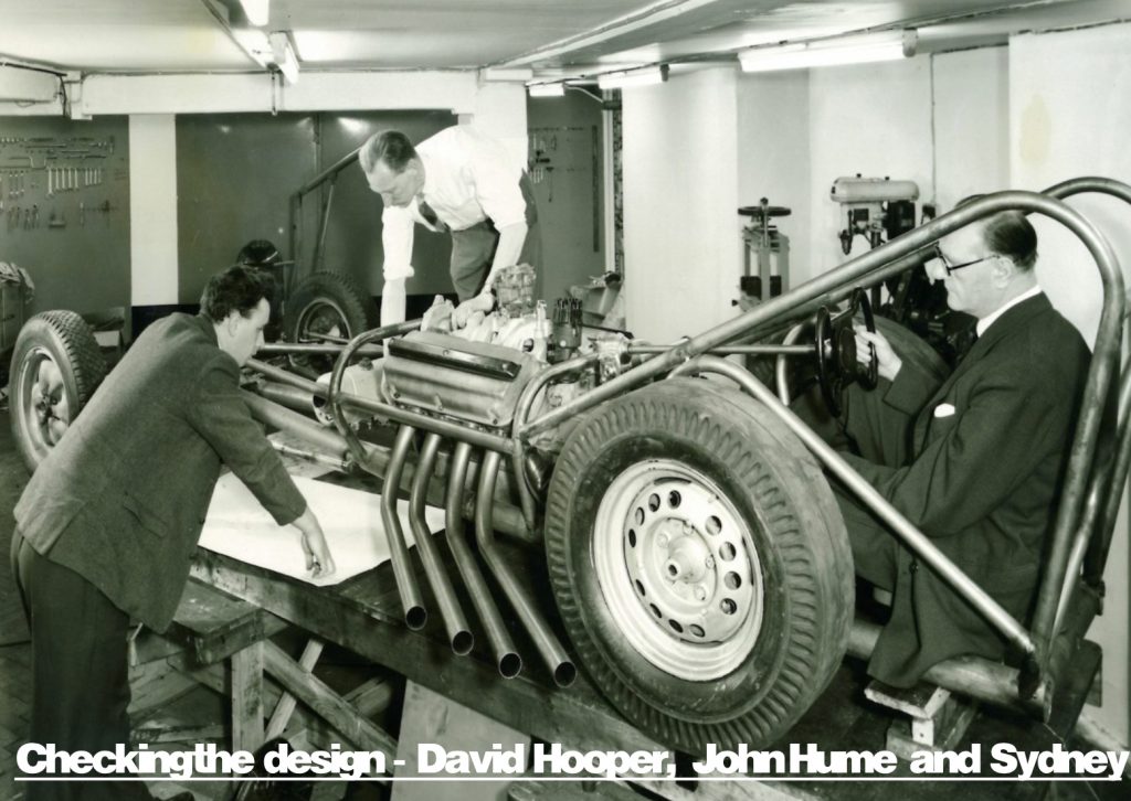
While it might have been possible to use a splined shaft and hub, the tapered shaft and keyway offered some advantages in allowing the maximum shaft diameter to be used. The shafts were made by Jack Knight Engineering at Battersea who had the added advantage, over our own machine shop, of being able to do gear cutting and source small quantities of hand forgings. The coupling between the gearbox and the rear axle was achieved by bolting together the two flanges from the Steyr ‘Sports Car’. This did not allow for any miss-alignment, however it did not give any trouble. In hind sight it would have been preferable to have used a coupling with peg drives similar to those I had used to connect the Alvis gearbox to the Salisbury 4HU differential unit fitted to Jim Tiller’s J2. The chassis was 3″ and 1.5″ diameter mild steel tubes with a substantial 1.5″ diameter by 10 SWG roll cage at the rear.