
Many years ago, Dudley Hume wrote about how to improve the cooling of our Flatheads. Chats with other owners confirmed it – I should follow Dudley’s “factory” advice for my M-type and not put up with the standard Ford setup.
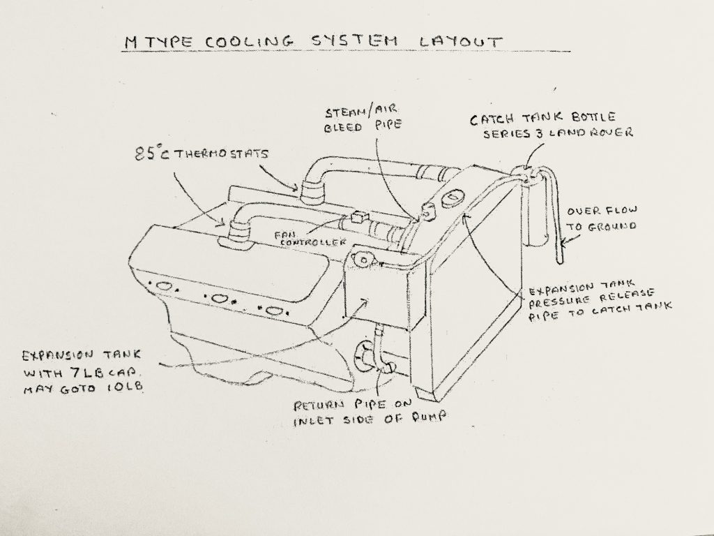
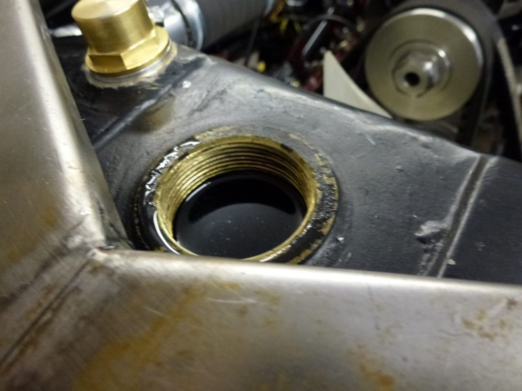
The radiator on my M Type has a screw-down cap in the centre and a separate pressure relief valve. This valve was removed and adapted to make a take off point for a small hose. The original overflow pipe down the radiator is blanked off and not used.
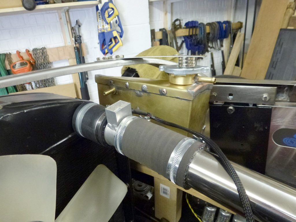
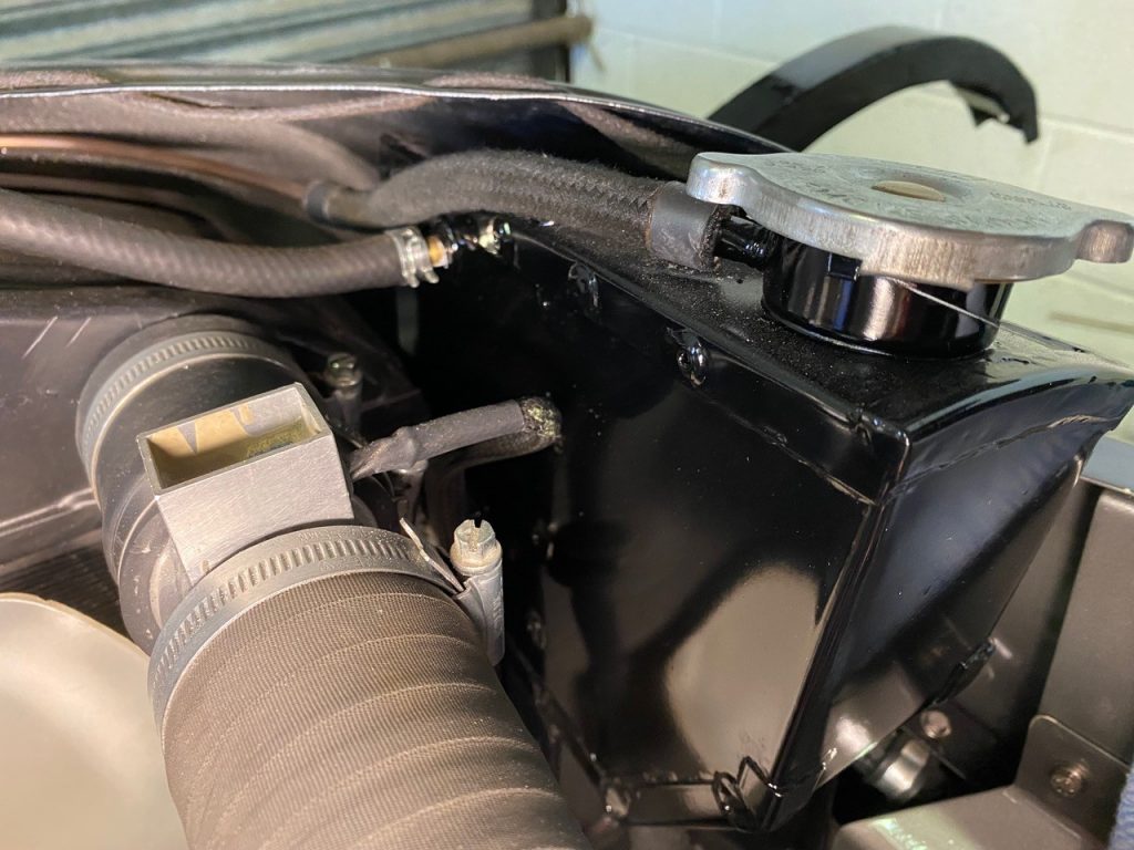
I made and fitted an expansion tank that sits next to the radiator on the right-hand side. The tank sits on three rubber isolation mounts, to allow for expansion and to stop vibration affecting the tank.
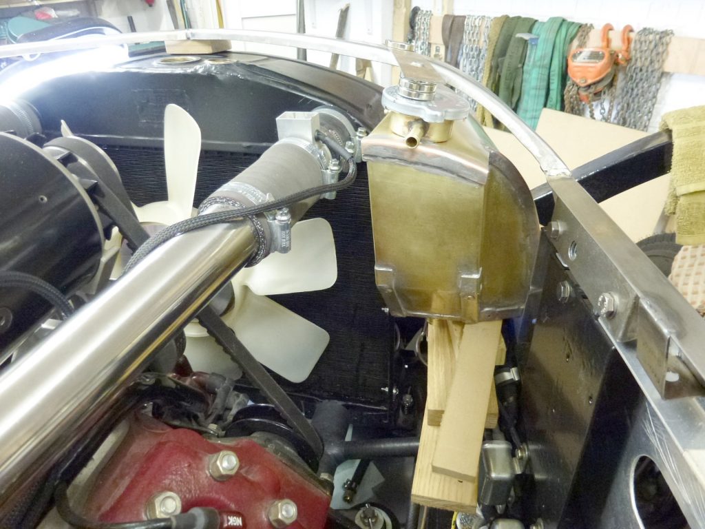
The tank itself was made from 1/16 brass sheet and fixed together with blind copper rivets together with soldered joints. The inside of the tank also has a reinforcing baffle tying all the sides together which is also soldered.
Editor’s note: Charles is an amazing craftsman. The rest of us may pay one of the many aluminium tank companies to make one.
There is a 7lb standard pressure cap on the top of the tank, angled to clear the curve of the bonnet with the overflow pipe pointing toward the radiator. This outlet will be connected to a catch tank situated on the left-hand side of the radiator.
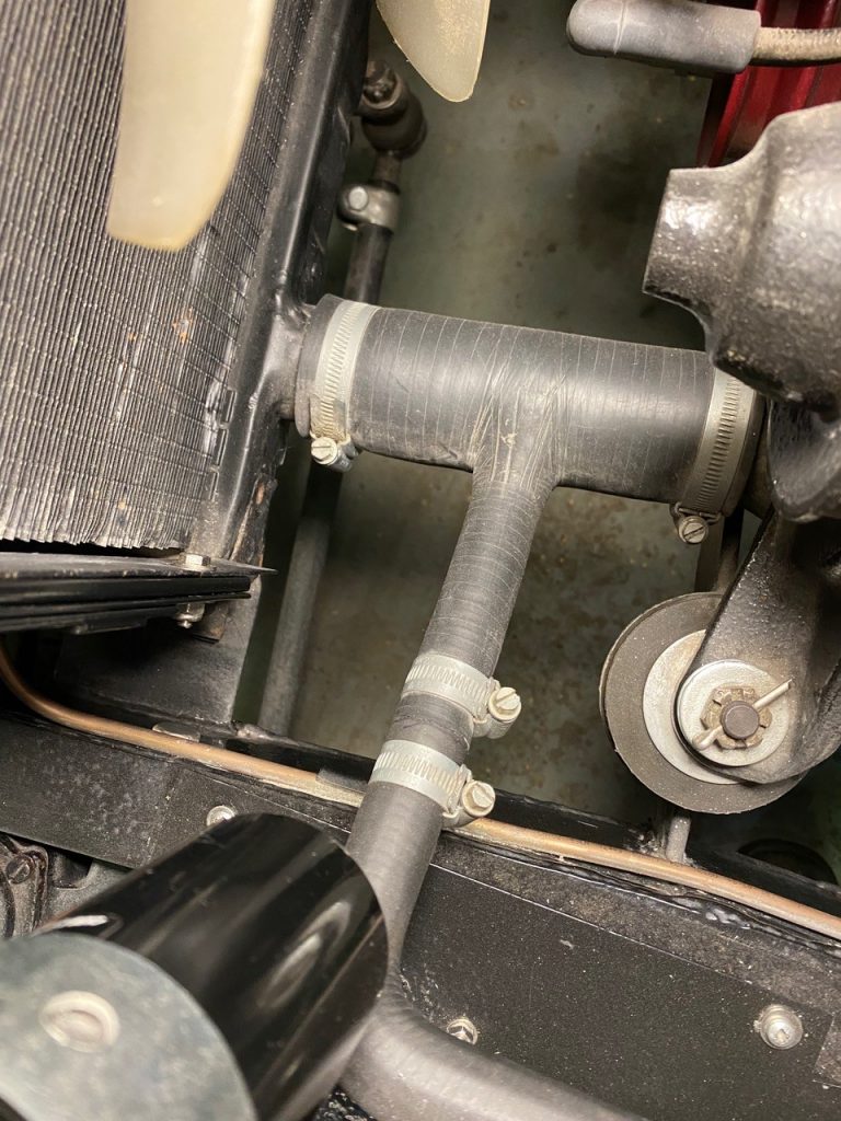
Then the take-off point which replaced the relief valve is now piped to the top of the expansion tank. The reason for doing this is to allow any trapped air or steam bubbles to vent out of the system to the expansion tank, so only water is in the radiator and no air at all if possible.
The 7lb pressure cap is situated just higher than the top of the radiator so any air etc should end up by the cap and be expelled when the cap releases (I hope).
Editor’s note: Every day is a school day: the expansion tank and the catch tank are two different things.
The bottom of the expansion tank has a 16mm dia hose attached which tees into the bottom hose that goes from the radiator to the right-hand water pump inlet. This has the effect of putting the expansion tank under a slight negative flow, because it is on the inlet side of the water pump. As water is taken from the bottom of the radiator a small amount will always be drawn from the expansion tank and will be replaced via the top vent pipe.
No water actually flows through the expansion tank as such, it’s basically static most of the time. If it was the other way round the expansion tank would be subjected to pump flow and positive pressure. Further to this it’s quite possible that the cap could lift on the expansion tank and eject water. This way the (pressure cap) is only subjected to pressure through temperature rise and expansion of water, not pump flow pressure.
There is also an expansion tank overflow bottle or “catch tank” fitted to the left-hand side of the radiator. With just over 1 litre capacity, it came from a Series 3 Land Rover. This is connected via a pipe to the outlet stub just below the 7Ib cap on the expansion tank.
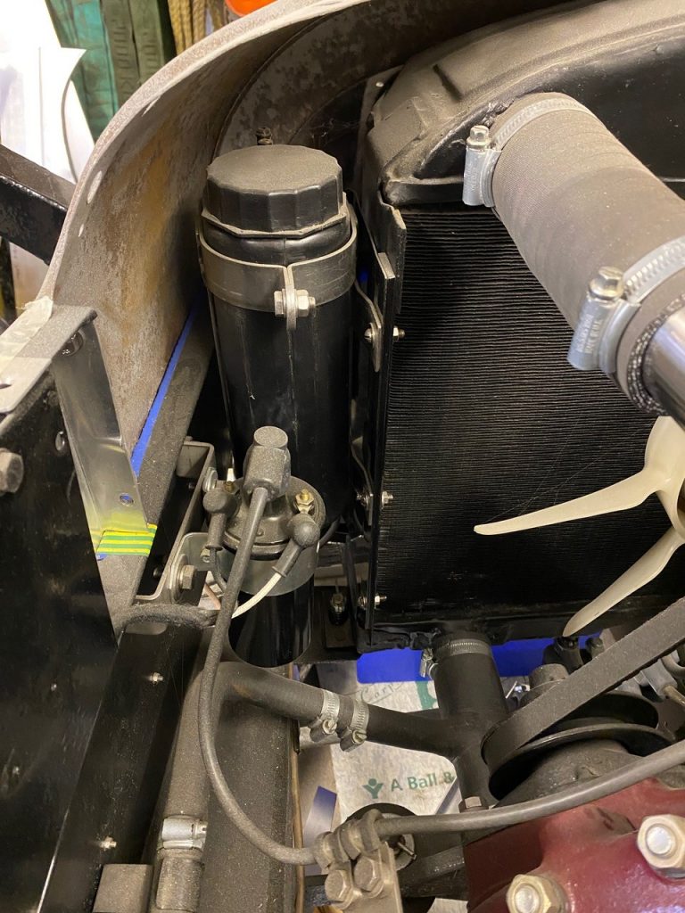
This in turn catches the expanded water as things heat up (about a litre at full temperature) with approximately 4-1/2 gallons / 20 litres in the system. This expelled water gets pulled back into the system when it cools down.
I fill the system with water right to the top of the radiator via its screw on cap. The radiator is always full of water with no air in the top.
I ran the engine up to temperature a few times and let it cool down. Each time the water level was found to be full to the brim and the maximum temperature seen on the gauge was about 190-195F. This was only in the garage but no matter how hard I tried I could not get it past 200deg F, though time will tell.
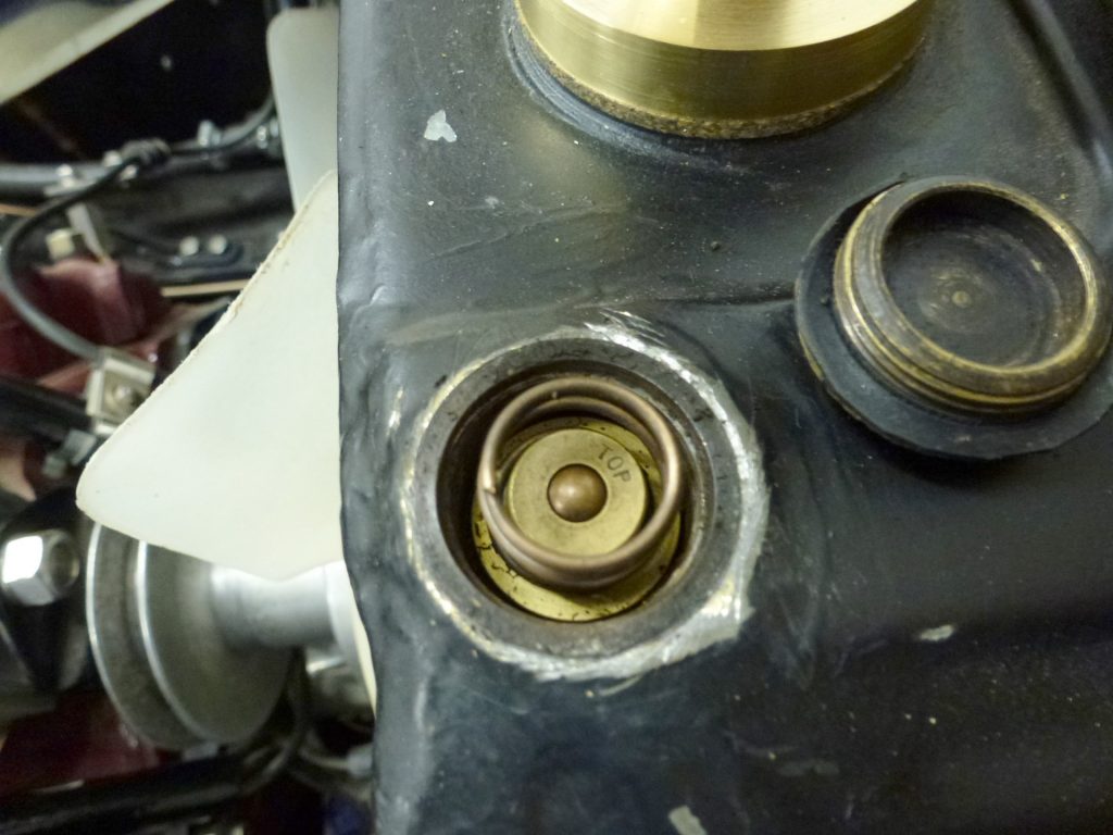
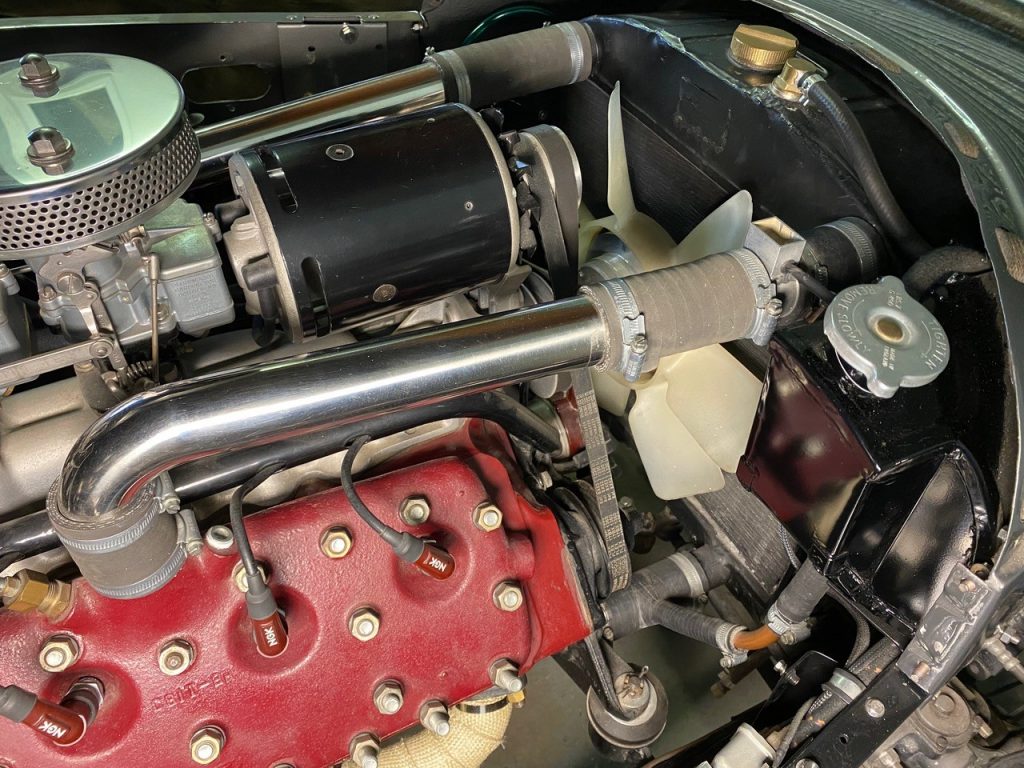
The two top hoses each incorporate a thermostat set at 85deg C / 180deg F and the water in the radiator is a 50/50 mix with standard blue antifreeze.
To test the system, I fitted a 15psi pressure gauge to the top of the radiator, put a catch bottle on the overflow from the expansion tank and filled the radiator to the brim. Within 5 minutes of starting the engine, the pressure rose to 2psi, which surprised me (the top hoses were still cold). After 10 minutes, and at 6psi, the thermostats started to open.
This resulted in the pressure dropping back to 5psi as the radiator was now in circuit. Things carried on warming up and at almost 7psi the expansion tank cap started to open and excess fluid was allowed to feed into a catch bottle below the car on the floor. The engine was allowed to run up to 195 deg on the water temp gauge. Two gallons of fuel was used during this test so everything was well and truly hot.
When the engine was turned off approx 1 ltr of water had been dumped into the catch bottle. What was interesting is this 1ltr of water appeared within 30mins of starting the engine and did not increase thereafter.
I left the car to cool down overnight and checked back the next day.
The fluid in the catch bottle had all gone, it had been returned to the expansion tank via the cap. I checked the level in the tank again and sure enough it was full to the brim. I carried out this test three or four times and the results were the same each time.
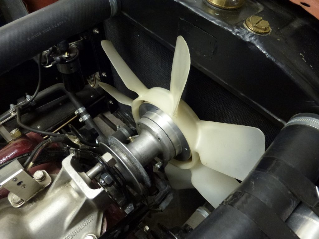
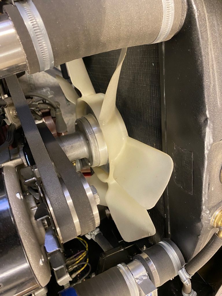
To supplement the cooling system I added a two-speed cooling fan in front of the radiator, a Tri Pac 14″ unit. The fan is not mounted on the radiator but stands off by about 2″ and is attached to the cross brace in front of the radiator.
The reason for doing it this way was to allow air to pass around the fan when it is not in use. I also changed the standard Ford pulley fan to a 7 blade Volvo 240 unit. This also allowed more clearance to the radiator about 1/2″, the standard Ford fan was way too close.
The air flow from this Volvo 7 bladed fan is quite something and sits on its own aluminium adaptor boss.
I did run this fan on low speed when doing the cooling checks to see what effect it would have. Just idling hot at the 195-200F mark it pulled 5-10deg off the temp in about a minute and dropped the pressure by 1psi from 6psi to 5psi. That surprised me as I did not think it would work that quickly. I will follow up with another article on how this cooling fan is controlled and the controller used.
I also found that the original relief valve not working or holding pressure, and at nearly 70 years old it’s not surprising.
Observations about modern car cooling
I did a lot of research into the cooling systems used in modern cars and what I described above is very similar. (Dudley knew what he was talking about).
Except one thing: on modern cars the temperature measurement is often a quarter of the way down the side of the radiator. Yet our gauges are fitted into the cylinder head water outlet pipe, right above the centre exhaust ports. Maybe this is not the best place for a sensor as it could be reading a higher temperature, rather than an average one at the radiator.